ВУЗ: Казахская Национальная Академия Искусств им. Т. Жургенова
Категория: Книга
Дисциплина: Не указана
Добавлен: 03.02.2019
Просмотров: 17450
Скачиваний: 51
depending on the desired sensitivity, and gold plated on one side. No
tensioning of the diaphragm was necessary inasmuch as the stiffness of
the thin glass was sufficient to maintain a high resonance frequency.
A more conventional capsule, the 11B was also used with the same base.
THE MICROPHONE BOOK
358
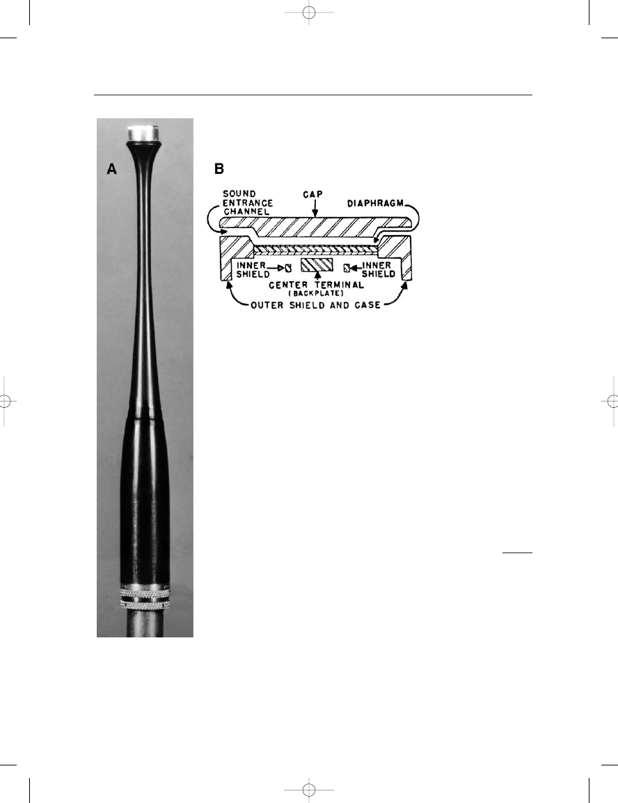
FIGURE 21–21
Altec Model M21 capacitor
microphone: photo of 150A
base with M21B capsule
(A); cutaway view of
capsule (B). (Photo courtesy
of William Hayes and
Micromike Labs.)
Earg_21.qxd 14/9/04 3:08 PM Page 358
21: Classic Microphones: The Author’s View
359
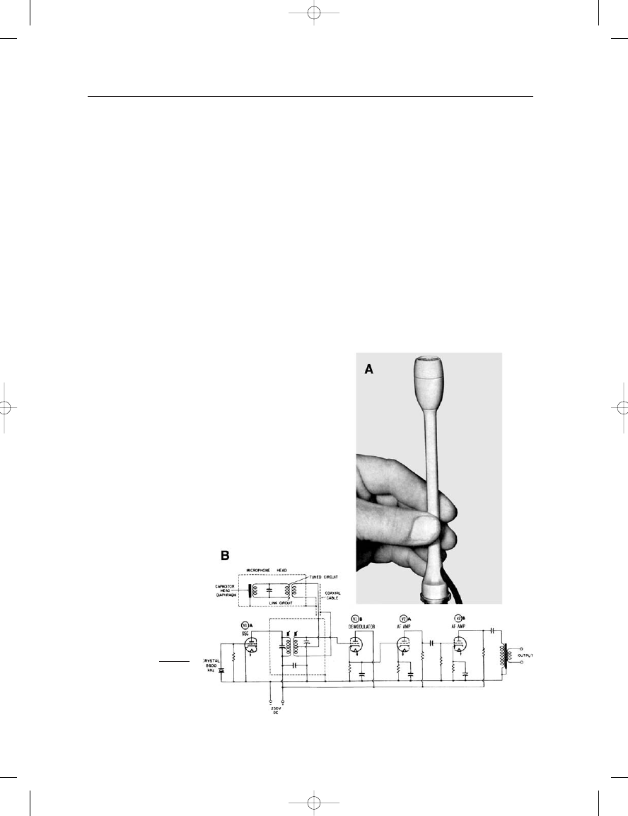
The Stephens Tru-Sonic company was founded in Los Angeles in the
1940s by Robert Stephens, who had worked with Lansing, Shearer, and
Hilliard on the academy award winning MGM loudspeaker system for
motion pictures. Like Lansing, he absorbed the manufacturing philoso-
phies and techniques that had been pioneered by Western Electric, and
his company was regarded during the 1950s in the same professional
class as Altec and JBL. In the early 1950s he introduced the first RF
microphone intended for recording and reinforcement activities, the model
C2-OD4. Figure 21–22A shows the C2 capsule assembly mounted on a
narrow stem, which was connected to the OD4 oscillator-demodulator
through a coaxial cable of any length – as long as the overall cable length
(transmission line) was a multiple of 37.5 inches – a requirement for effi-
cient signal transfer from the capsule to the demodulator. The schematic
of the oscillator-demodulator is shown at B, and it can be seen that the
capsule portion contained only the half-inch (12 mm) diaphragm closely
coupled to an oscillating tank circuit. The system operated on the FM
FIGURE 21–22
Stephens Model C2-OD4
RF microphone. (Photo A
from Read, 1952; data at B
from Tremaine, 1969.)
Earg_21.qxd 14/9/04 3:08 PM Page 359
principle in the range of 9 MHz, and signal demodulation took place in
the associated circuitry.
The system had excellent performance characteristics but exhibited
certain reliability problems due to shifts in the operating characteristics
of the vacuum tubes in the electronics unit. The microphone was a
favorite of such notables as Ewing Nunn, producer of Audiophile record-
ings, and Paul Klipsch, noted loudspeaker manufacturer and recording
enthusiast. Perhaps because of the long term stability problem, relatively
few of these microphones were built.
Frank Capps had worked for Edison in his phonograph division, and
when that company closed in 1929 Capps founded a company whose
THE MICROPHONE BOOK
360
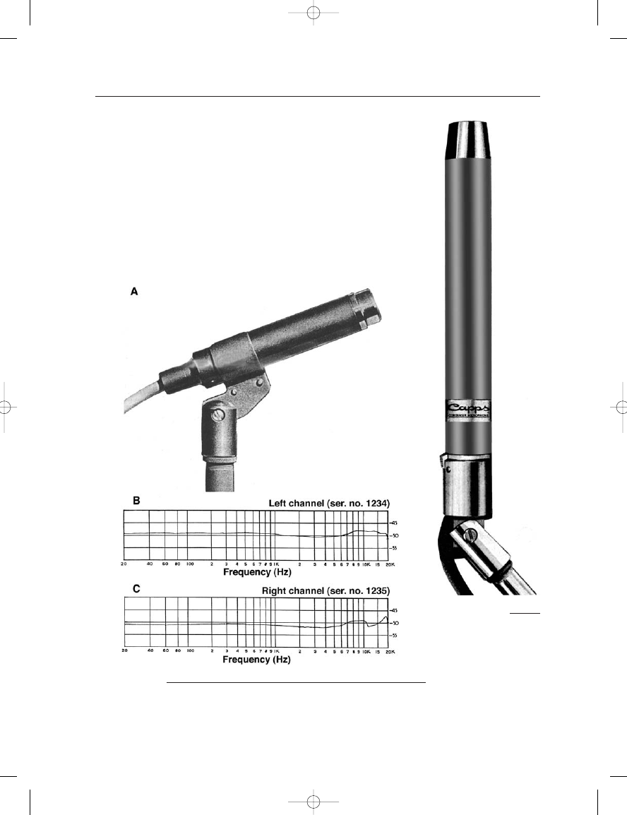
FIGURE 21–23
Capps Model CM2250
microphone. (Data from
company advertising.)
FIGURE 21–24
Stanford-Omega Condenser Microphone: view of microphone (A); frequency response
curves for a stereo pair (B and C). (Data provided by Lowell Cross.)
Earg_21.qxd 14/9/04 3:08 PM Page 360
21: Classic Microphones: The Author’s View
361
single product was cutting styli for disc recording. In the early 1950s the
company developed the model CM2250 capacitor omni shown in
Figure 21–23. The design was elegant and the tapered capsule assembly
was easily spotted at some distance. Emory Cook, of Cook Laboratories,
used a pair of these microphones in virtually all of his early audiophile
and ethnic music recordings.
Marketed under the name Stanford-Omega, the Thompson Omega
company in southern California manufactured the microphone shown in
Figure 21–24A. The microphone carried no model number and was
known only as the Stanford-Omega Condenser Microphone. The manu-
facturer did something that very few companies do today – they pro-
vided actual calibration curves on each microphone. Curves for a typical
stereo pair are shown at B and C.
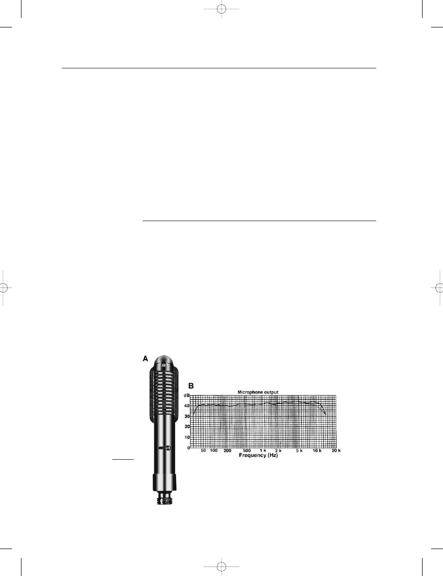
BANG&OLUFSEN MODEL BM-3
The Danish Bang&Olufsen company is primarily noted for high perform-
ance home high fidelity equipment elegantly representative of modern
Scandinavian industrial design. As far back as the early 1950s the com-
pany was experimenting with stereo, and a variety of ribbon microphones,
both mono and stereo, were built by the company. Compared with the
relatively large ribbons of the mid 1950s, the B&O models were fairly
small, and response beyond 10 kHz was maintained. The microphone was
made famous by the many articles written by Erik Madsen (1957) in both
the technical and popular press in which a spaced pair of these micro-
phones were deployed with a directional baffle (see Figure 12–9A).
Figure 21–25A shows a view of the BM-3 model; response curves,
with and without the protective mesh grille, are shown at B. Note the
smooth response and HF extension beyond 10 kHz. The exposed flanges
FIGURE 21–25
B&O Model BM-3 ribbon
microphone: Photo (A);
frequency response (B).
(Data from B&O
specification sheet.)
Earg_21.qxd 14/9/04 3:08 PM Page 361
on each side of the grille structure are actually magnetic return paths
around the ribbon.
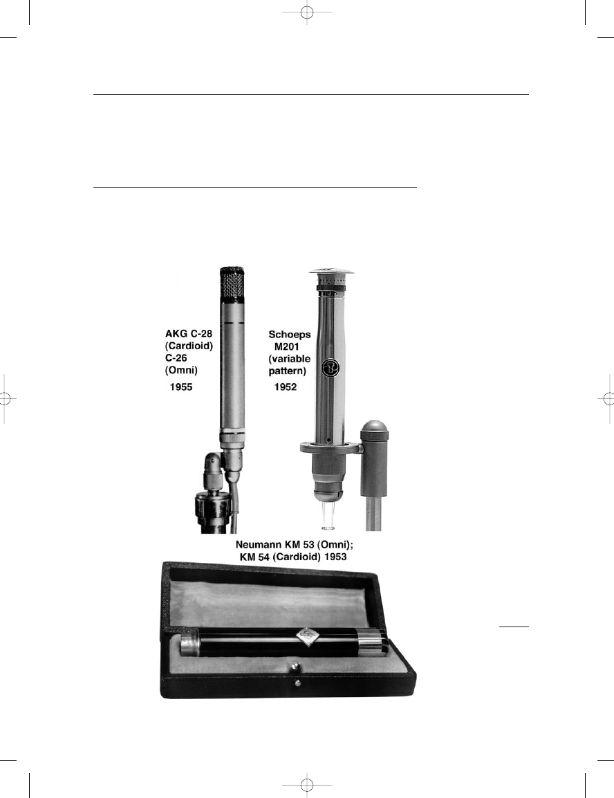
THE RISE OF SMALL FORMAT CAPACITOR
MICROPHONES
The first capacitor microphones for studio applications were fairly large
models, most of them with switchable pickup patterns. During the early
to mid 1950s three companies, AKG, Schoeps, and Neumann introduced
smaller format designs with capsules in the diameter range 15–18 mm
THE MICROPHONE BOOK
362
FIGURE 21–26
The earliest small format
capacitor microphones
from AKG, Schoeps
and Neumann. (Photos
courtesy of the
manufacturers.)
Earg_21.qxd 14/9/04 3:09 PM Page 362