ВУЗ: Казахская Национальная Академия Искусств им. Т. Жургенова
Категория: Книга
Дисциплина: Не указана
Добавлен: 03.02.2019
Просмотров: 17449
Скачиваний: 51

SYMBOLS USED IN THIS BOOK
a
radius of diaphragm (mm); acceleration (m/s
2
)
A
ampere (unit of electrical current)
AF
audio frequency
c
speed of sound (334 m/s at normal temperature)
C
temperature (degrees celsius)
d
distance (m)
dB
relative level (decibel)
dB(A)
A-weighted sound pressure level
dBu
signal voltage level (re 0.775 volt rms)
D
C
critical distance (m)
DI
directivity index (dB)
E
voltage (volt dc)
e(t)
signal voltage (volt rms)
f
frequency in hertz (s
–1
)
HF
high frequency
Hz
frequency (hertz, cycles per second)
I
acoustical intensity (W/m
2
)
I
dc electrical current, ampere (Q/s)
i(t)
signal current (ampere rms)
I
0
mechanical moment of inertia (kg
m
2
)
j
complex algebraic operator, equal to
k
wave number (2
/)
kg
mass, kilogram (SI base unit)
K
temperature (degrees kelvin, SI base unit)
LF
low frequency
L
P
sound pressure level (dB re 20
Pa)
L
R
reverberant sound pressure level (dB re 20
Pa)
L
N
noise sound pressure level (dB re 20
Pa)
m
meter (SI base unit)
MF
mid frequency
mm
millimeter (m
10
–3
)
m
micrometer or micron (m
10
–6
)
1
Earg_FM.qxd 14/9/04 3:11 PM Page x

M
microphone system sensitivity, mV/Pa
M
D
capacitor microphone base diaphragm sensitivity, V/Pa
N
force, newton (kg, m/s
2
)
p; p(t)
rms sound pressure (N/m
2
)
P
power (watt)
Q
electrical charge (coulombs, SI base unit)
Q
directivity factor
r
distance from sound source (m)
R,
electrical resistance (ohm)
R
room constant (m
3
or ft
3
)
RE
random efficiency of microphone (also REE)
RF
radio frequency
RH
relative humidity (%)
s
second (SI base unit)
S
surface area (m
2
)
T
torque (N
m)
T, t
time (s)
T
magnetic flux density (tesla)
T
60
reverberation time (seconds)
T
0
diaphragm tension (newton/meter)
torr
atmospheric pressure; equal to mm of mercury (mmHg), or
133.322 Pa (Note: 760 torr is equal to normal atmospheric
pressure at 0
C)
u; u(t)
air particle rms velocity (m/s)
U, U(t)
air volume rms velocity (m
3
/s)
x(t)
air particle displacement (m/s)
X
mechanical, acoustical, or electrical reactance (
)
V
electrical voltage (voltage or potential)
Z
mechanical, acoustical or electrical resistance (
)
average absorption coefficient (dimensionless)
wavelength of sound in air (m)
phase, phase shift (degrees or radians)
dependent variable in polar coordinates
0
density of air (1.18 kg/m
3
)
0
c
specific acoustical impedance of air (415 SI rayls)
angle (degrees or radians), independent variable in polar
coordinates
2
f (angular frequency in radians/s)
m
surface mass density (kg/m
2
)
Symbols Used in This Book
xi
Earg_FM.qxd 14/9/04 3:11 PM Page xi

Earg_FM.qxd 14/9/04 3:11 PM Page xii

C
H
A
P
T
E
R
1
A SHORT HISTORY OF THE
MICROPHONE
INTRODUCTION
The microphone pervades our daily lives through the sound we hear on
radio, television and recordings, paging in public spaces, and of course
in two-way communications via telephone. In this chapter we will touch
upon some of the highlights of more than 125 years of microphone
development, observing in particular how most of the first 50 of these
years were without the benefits of electronic amplification. The require-
ments of telephony, radio broadcast, general communications, and
recording are also discussed, leading to some conjecture on future
requirements.
THE EARLY YEARS
As children, many of us were fascinated with strings stretched between
the ends of a pair of tin cans or wax paper cups, with their ability to con-
vey speech over a limited distance. This was a purely mechano-acoustical
arrangement in which vibrations generated at one end were transmitted
along the string to actuate vibrations at the other end.
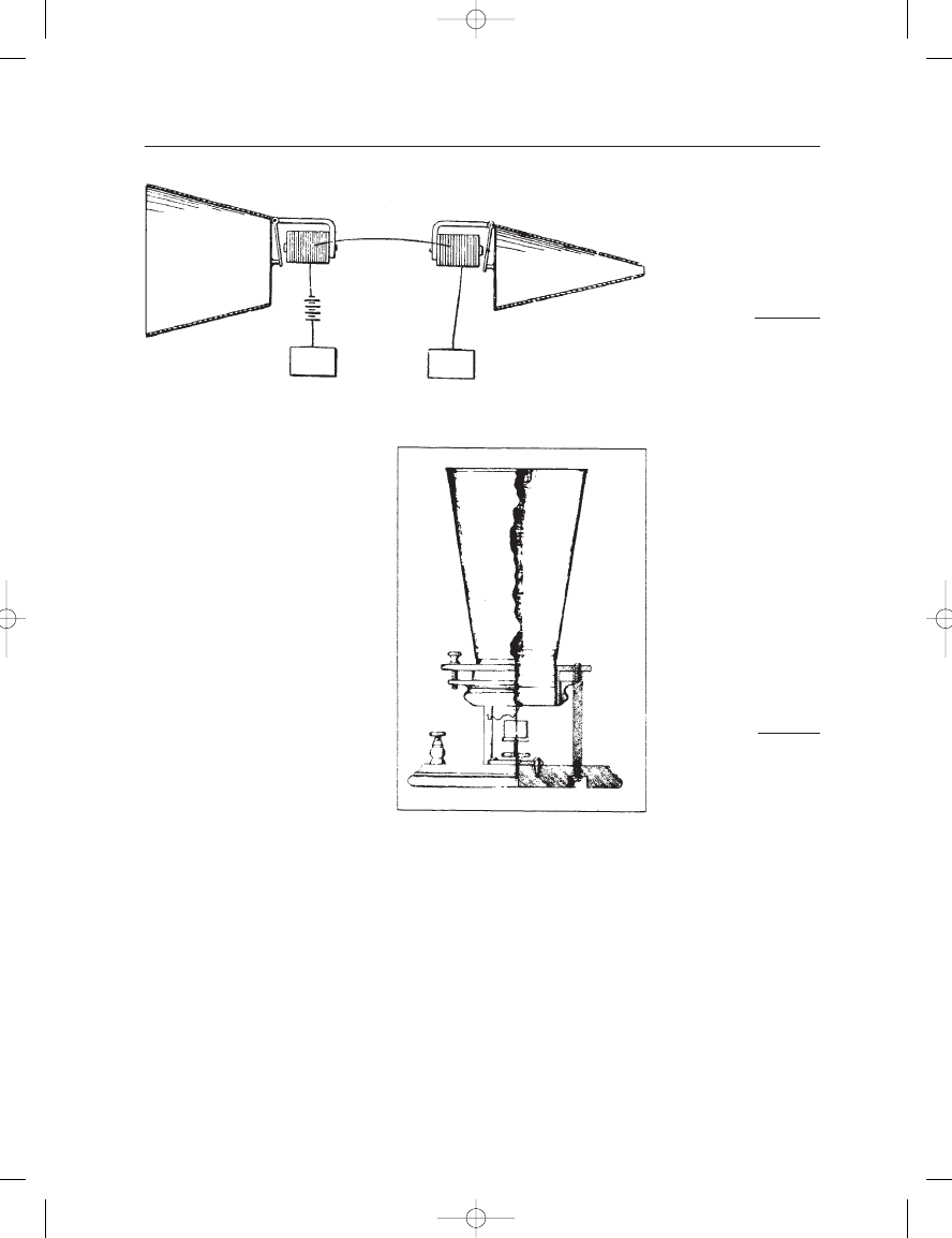
In 1876, Alexander Graham Bell received US patent 174,465 on the
scheme shown in Figure 1–1. Here, the mechanical string was, in a sense,
replaced by a wire that conducted electrical direct current, with audio
signals generated and received via a moving armature transmitter and its
associated receiver. Like the mechanical version, the system was reci-
procal. Transmission was possible in either direction; however, the
patent also illustrates the acoustical advantage of a horn to increase the
driving pressure at the sending end and a complementary inverted horn
to reinforce output pressure at the ear at the receiving end. Bell’s further
experiments with the transmitting device resulted in the liquid transmitter,
Earg_01.qxd 14/9/04 2:34 PM Page 1
shown in Figure 1–2, which was demonstrated at the Philadelphia
Centennial Exposition of 1876. Here, the variable contact principle
provided a more effective method of electrical signal modulation than
that afforded by the moving armature.
The variable contact principle was extended by Berliner in a patent
application in 1877 in which a steel ball was placed against a stretched
metal diaphragm, as shown in Figure 1–3. Further work in this area was
done by Blake (patents 250, 126 through 250, 129, issued in 1881), who
used a platinum bead impressed against a hard carbon disc as the vari-
able resistance element, as shown in Figure 1–4. The measured response
of the Blake device spanned some 50 decibels over the frequency range
THE MICROPHONE BOOK
2
FIGURE 1–1
The beginnings of
telephony; Bell’s
original patent.
FIGURE 1–2
Bell’s liquid transmitter
exhibited at the
Philadelphia Centennial
Exposition of 1876.
Earg_01.qxd 14/9/04 2:34 PM Page 2