ВУЗ: Казахская Национальная Академия Искусств им. Т. Жургенова
Категория: Книга
Дисциплина: Не указана
Добавлен: 03.02.2019
Просмотров: 17451
Скачиваний: 51
1: A Short History of the Microphone
3
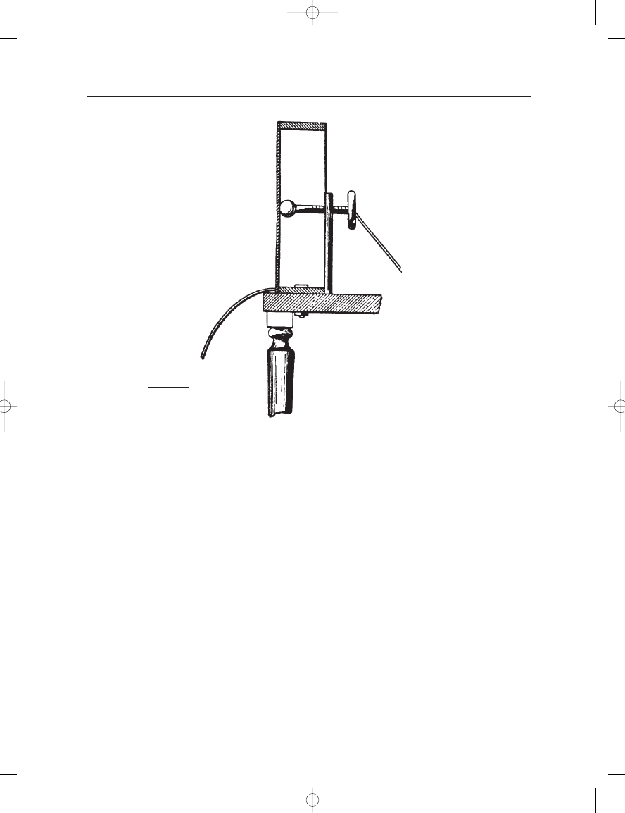
FIGURE 1–3
Berliner’s variable
contact microphone.
from 380 Hz to 2000 Hz, and thus fell far short of the desired response.
However, it provided a more efficient method of modulating telephone
signals than earlier designs and became a standard in the Bell system for
some years.
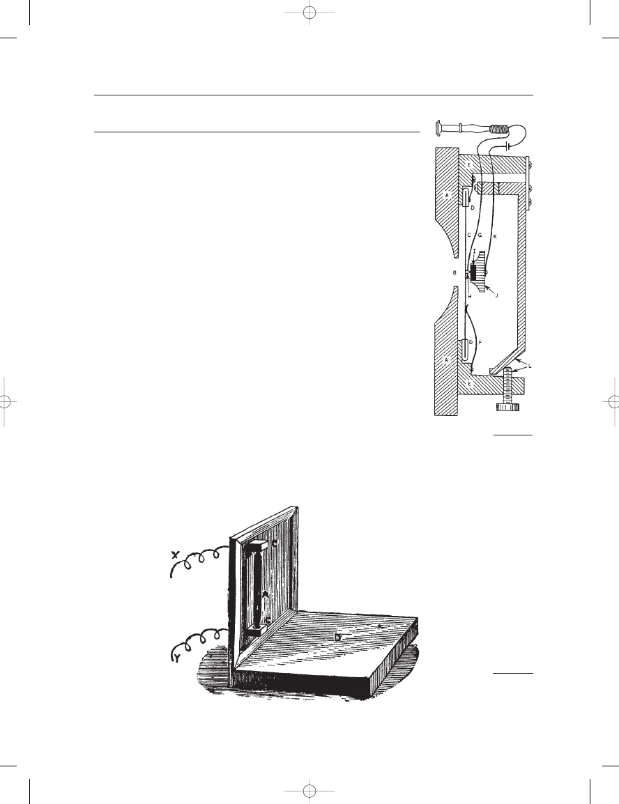
Another interim step in the development of loose contact modula-
tion of direct current was developed in 1878 by Hughes and is shown in
Figure 1–5. In this embodiment, very slight changes in the curvature of
the thin wood plate diaphragm, caused by impinging sound waves, gave
rise to a fairly large fluctuation in contact resistance between the carbon
rod and the two mounting points. This microphone was used by Clement
Ader (Scientific American, 1881) in his pioneering two-channel trans-
missions from the stage of the Paris Opera to a neighboring space. It was
Hughes, incidentally, who first used the term microphone, as applied to
electroacoustical devices.
The ultimate solution to telephone transmitters came with the devel-
opment of loose carbon granule elements as typified by Blake’s transmitter
of 1888, shown in Figure 1–6. Along with the moving armature receiver,
the loose carbon granule transmitter, or microphone, has dominated
telephony up to the present. Quite a testimony to the inventiveness and
resourcefulness of engineers working nearly 130 years ago.
Earg_01.qxd 14/9/04 2:34 PM Page 3
THE RISE OF BROADCASTING
The carbon granule transmitter and moving armature receiver comple-
mented each other nicely. The limitations in bandwidth and dynamic
range have never been a problem in telephony, and the rather high dis-
tortion generated in the combined systems actually improved speech
intelligibility by emphasizing higher frequencies. Even after the invention
of electronic amplification (the de Forest audion vacuum tube, 1907),
these earlier devices remained in favor.
When commercial broadcasting began in the early 1920s, there was
a clear requirement for better microphones as well as loudspeakers.
Western Electric, the manufacturing branch of the Bell Telephone system,
was quick to respond to these needs, developing both electrostatic
(capacitor) microphones as well as electrodynamic (moving conductor)
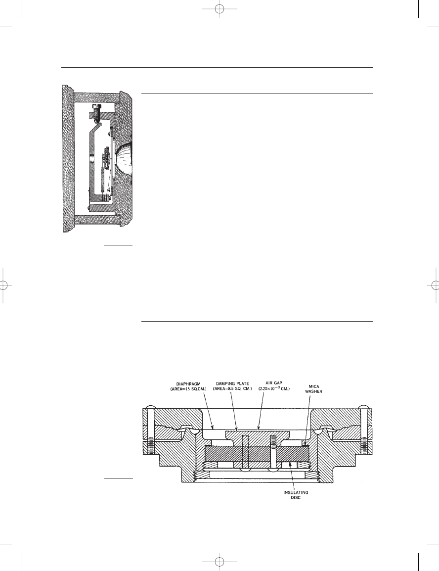
microphones. The capacitor, or condenser, microphone used a fixed elec-
trical charge on the plates of a capacitor, one of which was a moving
diaphragm and the other a fixed back plate. Sound waves caused a slight
variation in capacitance, which in turn was translated into a variation in
the voltage across the plates. An early Western Electric capacitor micro-
phone, developed by Wente in 1917, is shown in Figure 1–7.
While first employed as a driving element for loudspeakers and
headphones, the moving coil and its close relative, the ribbon, eventually
found their place in microphone design during the mid-twenties. Moving
coil and ribbon microphones operate on the same principle; the electri-
cal conducting element is place in a transverse magnetic field, and its
motion generated by sound vibrations induces a voltage across the con-
ducting element. Under the direction of Harry Olson, Radio Corporation
of America (RCA) was responsible for development and beneficial
exploitation of the ribbon microphone during the 1930s and 1940s.
THE MICROPHONE BOOK
4
FIGURE 1–5
Hughes’ carbon rod
microphone.
FIGURE 1–4
Blake’s carbon disc
microphone.
Earg_01.qxd 14/9/04 2:34 PM Page 4
THE RISE OF MASS COMMUNICATIONS
Beginning as far back as the 1920s, a number of smaller American com-
panies, such as Shure Brothers and Electro-Voice, began to make signifi-
cant contributions to microphone engineering and design. General
applications, such as paging and sound reinforcement, required ingen-
ious and economical solutions to many problems. Commercial develop-
ment of capacitor microphones was more or less ruled out, due to the
requirements for a cumbersome polarizing supply, so these companies
concentrated primarily on moving coil designs.
The work of Bauer (1941) was significant in producing the Shure
Unidyne directional (cardioid pattern) design based on a single moving
coil element. Wiggins (1954) developed the Electro-Voice “Variable-D”
single moving coil element, which provided low handling noise with
excellent directional response.
Other companies designed crystal microphones for low cost,
moderate-quality paging applications. These designs were based on the
principle of piezoelectricity (from the Greek piezien, meaning pressure),
which describes the property of many crystalline structures to develop a
voltage across opposite facets when the material is bent or otherwise
deformed. The early advantage of the piezos was a relatively high output
signal, but eventually the coming of small, high energy magnet materials
ruled them out.
THE GREAT CAPACITOR BREAKTHROUGH:
THE ELECTRET
For many years the penalty carried by the capacitor microphone was its
requirement for external polarization voltage. In the early sixties, Sessler
and West of Bell Telephone Laboratories described a capacitor micro-
phone which used a permanently polarized dielectric material between
1: A Short History of the Microphone
5
FIGURE 1–6
Blake’s variable
contact microphone.
FIGURE 1–7
The Wente capacitor
microphone of 1917.
Earg_01.qxd 14/9/04 2:34 PM Page 5

the movable diaphragm and the backplate of the microphone. Early
materials exhibited significant losses in sensitivity over time, but these
problems have been overcome. Further improvements have come in
miniaturization, enabling electret microphones to be designed for a wide
variety of close-in applications, such as tie-tack use, hidden on-stage
pickup, and many other uses. Today’s small electret microphone requires
only a miniature self-contained 5-to-9 volt battery to power its equally
miniature preamplifier. It is a testimony to the electret and its long-term
stability and excellent technical performance that the Brüel & Kjaer series
of studio microphones designed in the 1980s used electret technology.
STUDIO MICROPHONE TECHNOLOGY
The microphone is the first stage in the complex and extended technical
chain between live performance and sound reproduction in the home
or motion picture theater. Little wonder then that so much attention
has been paid to the quality and technical performance of these fine
instruments.
Capacitor microphones have dominated studio recording since the
late 1940s when the first German and Austrian capacitor microphones
came on the scene. As with any mature technology, progress comes
slowly, and the best models available today have a useful dynamic range
that exceeds that of a 20-bit digital recorder. With regard to directional
performance, many newer microphones exhibit off-axis response
integrity that far exceeds the best of earlier models.
At the beginning of the 21st century, it is interesting to observe
the great nostalgia that many recording engineers have for the earlier
vacuum tube capacitor models, especially the Neumann and AKG classic
microphones of the 1950s. All of this reminds us that technology is so
often tempered with subjective judgment to good effect.
THE FUTURE
The microphone per se is so highly developed that it is often difficult to
see where specific improvements in the basic mechanisms are needed.
Certainly in the area of increased directionality, via second and higher
order designs, is there additional development engineering to be done.
There may never be a direct-converting, high-quality digital microphone
as such, but it is clear that digital signal processing will certainly play an
important part in active microphone array development.
New usage concepts include microphones in conferencing systems,
with their requirements for combining and gating of elements; and
microphones in large arrays, where highly directional, steerable pickup
patterns can be realized. These are among the many subjects that will be
discussed in later chapters.
THE MICROPHONE BOOK
6
Earg_01.qxd 14/9/04 2:34 PM Page 6

C
H
A
P
T
E
R
2
BASIC SOUND
TRANSMISSION AND
OPERATIONAL FORCES
ON MICROPHONES
INTRODUCTION
All modern microphones benefit from electrical amplification and thus
are designed primarily to sample a sound field rather than take power
from it. In order to understand how microphones work from the physi-
cal and engineering points of view, we must understand the basics of
sound transmission in air. We base our discussion on sinusoidal wave
generation, since sine waves can be considered the building blocks of
most audible sound phenomena. Sound transmission in both plane and
spherical waves will be discussed, both in free and enclosed spaces.
Power relationships and the concept of the decibel are developed. Finally,
the effects of microphone dimensions on the behavior of sound pickup
are discussed.
BASIC WAVE GENERATION AND
TRANSMISSION
Figure 2–1 illustrates the generation of a sine wave. The vertical compo-
nent of a rotating vector is plotted along the time axis, as shown at A.
At each 360
of rotation, the wave structure, or waveform, begins anew.
The amplitude of the sine wave reaches a crest, or maximum value,
above the zero reference baseline, and the period is the time required for
the execution of one cycle. The term frequency represents the number of
cycles executed in a given period of time. Normally we speak of fre-
quency in hertz (Hz), representing cycles per second.
Earg_02.qxd 14/9/04 2:35 PM Page 7