ВУЗ: Казахская Национальная Академия Искусств им. Т. Жургенова
Категория: Книга
Дисциплина: Не указана
Добавлен: 03.02.2019
Просмотров: 21565
Скачиваний: 19

1-21
Chapter
1.2
Sound Propagation
Floyd E. Toole
E. A. G. Shaw, G. A. Daigle, M. R. Stinson
1.2.1
Introduction
Sound propagating away from a source diminishes in strength at a rate determined by a variety of
circumstances. It also encounters situations that can cause changes in amplitude and direction.
Simple reflection is the most obvious process for directional change, but with sound there are
also some less obvious mechanisms.
1.2.2
Inverse-Square and Other Laws
At increasing distances from a source of sound the level is expected to decrease. The rate at
which it decreases is dictated by the directional properties of the source and the environment into
which it radiates. In the case of a source of sound that is small compared with the wavelength of
the sound being radiated, a condition that includes many common situations, the sound spreads
outward as a sphere of ever-increasing radius. The sound energy from the source is distributed
uniformly over the surface of the sphere, meaning that the intensity is the sound power output
divided by the surface area at any radial distance from the source. Because the area of a sphere is
4
πr
2
, the relationship between the sound intensities at two different distances is
(1.2.1)
where I
1
= intensity at radius r
1
, I
2
= intensity at radius r
2
, and
(1.2.2)
I
1
I
2
----
r
2
2
r
1
2
----
=
Level difference
10 log
r
2
2
r
1
2
----
20 log
r
2
r
1
---- dB
=
=
Downloaded from Digital Engineering Library @ McGraw-Hill (www.digitalengineeringlibrary.com)
Copyright © 2004 The McGraw-Hill Companies. All rights reserved.
Any use is subject to the Terms of Use as given at the website.
Source: Standard Handbook of Audio and Radio Engineering

1-22 Principles of Sound and Hearing
This translates into a change in sound level of 6 dB for each doubling or halving of distance, a
convenient mnemonic.
In practice, however, this relationship must be used with caution because of the constraints of
real environments. For example, over long distances outdoors the absorption of sound by the
ground and the air can modify the predictions of simple theory [1]. Indoors, reflected sounds can
sustain sound levels to greater distances than predicted, although the estimate is correct over
moderate distances for the direct sound (the part of the sound that travels directly from source to
receiver without reflection). Large sound sources present special problems because the sound
waves need a certain distance to form into an orderly wave-front combining the inputs from vari-
ous parts of the source. In this case measurements in what is called the near field may not be rep-
resentative of the integrated output from the source, and extrapolations to greater distances will
contain errors. In fact the far field of a source is sometimes defined as being distances at which
the inverse-square law holds true. In general, the far field is where the distance from the source is
at least 2 to 3 times the distance between the most widely separated parts of the sound source that
are radiating energy at the same frequency.
If the sound source is not small compared with the wavelength of the radiated sound, the
sound will not expand outward with a spherical wavefront and the rate at which the sound level
reduces with distance will not obey the inverse-square law. For example, a sound source in the
form of a line, such as a long column of loudspeakers or a long line of traffic on a highway, gen-
erates sound waves that expand outward with a cylindrical wavefront. In the idealized case, such
sounds attenuate at the rate of 3 dB for each doubling of distance.
1.2.3
Sound Reflection and Absorption
A sound source suspended in midair radiates into a free field because there is no impediment to
the progress of the sound waves as they radiate in any direction. The closest indoor equivalent of
this is an anechoic room, in which all the room boundaries are acoustically treated to be highly
absorbing, thus preventing sounds from being reflected back into the room. It is common to
speak of such situations as sound propagation in full space, or 4
π steradians (sr; the units by
which solid angles are measured).
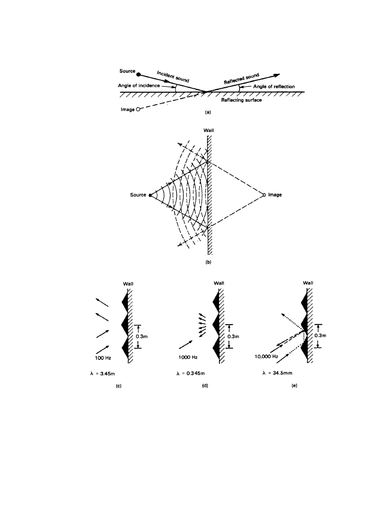
In normal environments sound waves run into obstacles, such as walls, and the direction of
their propagation is changed. Figure 1.2.1 shows the reflection of sound from various surfaces. In
this diagram the pressure crests of the sound waves are represented by the curved lines, spaced
one wavelength apart. The radial lines show the direction of sound propagation and are known as
sound rays. For reflecting surfaces that are large compared with the sound wavelength, the nor-
mal law of reflection applies: the angle that the incident sound ray makes with the reflecting sur-
face equals the angle made by the reflected sound ray.
This law also holds if the reflecting surface has irregularities that are small compared with the
wavelength, as shown in Figure 1.2.1c, where it is seen that the irregularities have negligible
effect. If, however, the surface features have dimensions similar to the wavelength of the incident
sound, the reflections are scattered in all directions. At wavelengths that are small compared with
the dimensions of the surface irregularities, the sound is also sent off in many directions but, in
this case, as determined by the rule of reflections applied to the geometry of the irregularities
themselves.
Downloaded from Digital Engineering Library @ McGraw-Hill (www.digitalengineeringlibrary.com)
Copyright © 2004 The McGraw-Hill Companies. All rights reserved.
Any use is subject to the Terms of Use as given at the website.
Sound Propagation
Sound Propagation 1-23
Figure 1.2.1
(
a) The relationship between the incident sound, the reflected sound, and a flat
reflecting surface, illustrating the law of reflection. (
b) A more elaborate version of (a), showing the
progression of wavefronts (the curved lines) in addition to the sound rays (arrowed lines). (
c) The
reflection of sound having a frequency of 100 Hz (wavelength 3.45 m) from a surface with irregu-
larities that are small compared with the wavelength. (
d) When the wavelength of the sound is sim-
ilar to the dimensions of the irregularities, the sound is scattered in all directions. (
e) When the
wavelength of the sound is small compared with the dimensions of the irregularities, the law of
reflection applies to the detailed interactions with the surface features.
Downloaded from Digital Engineering Library @ McGraw-Hill (www.digitalengineeringlibrary.com)
Copyright © 2004 The McGraw-Hill Companies. All rights reserved.
Any use is subject to the Terms of Use as given at the website.
Sound Propagation

1-24 Principles of Sound and Hearing
If there is perfect reflection of the sound, the reflected sound can be visualized as having orig-
inated at an image of the real source located behind the reflector and emitting the same sound
power. In practice, however, some of the incident sound energy is absorbed by the reflecting sur-
face; this fraction is called the sound absorption coefficient of the surface material. A coefficient
of 0.0 indicates a perfect reflector, and a coefficient of 1.0 a perfect absorber; intermediate val-
ues indicate the portion of the incident sound energy that is dissipated in the surface and is not
reflected. In general, the sound absorption coefficient for a material is dependent on the fre-
quency and the angle of incidence of the sound. For simplicity, published values are normally
given for octave bands of frequencies and for random angles of incidence.
1.2.3a
Interference: The Sum of Multiple Sound Sources
The principle of superposition states that multiple sound waves (or electrical signals) appearing
at the same point will add linearly. Consider two sound waves of identical frequency and ampli-
tude arriving at a point in space from different directions. If the waveforms are exactly in step
with each other, i.e., there is no phase difference, they will add perfectly and the result will be an
identical waveform with double the amplitude of each incoming sound (6-dB-higher SPL). Such
in-phase signals produce constructive interference. If the waveforms are shifted by one-half
wavelength (180° phase difference) with respect to each other, they are out of phase; the pressure
fluctuations are precisely equal and opposite, destructive interference occurs, and perfect cancel-
lation results.
In practice, interference occurs routinely as a consequence of direct and reflected sounds add-
ing at a microphone or a listener's ear. The amplitude of the reflected sound is reduced because
of energy lost to absorption at the reflecting surface and because of inverse-square-law reduction
related to the additional distance traveled. This means that constructive interference yields sound
levels that are increased by less than 6 dB and that destructive interference results in imperfect
cancellations that leave a residual sound level. Whether the interference is constructive or
destructive depends on the relationship between the extra distance traveled by the reflection and
the wavelength of the sound.
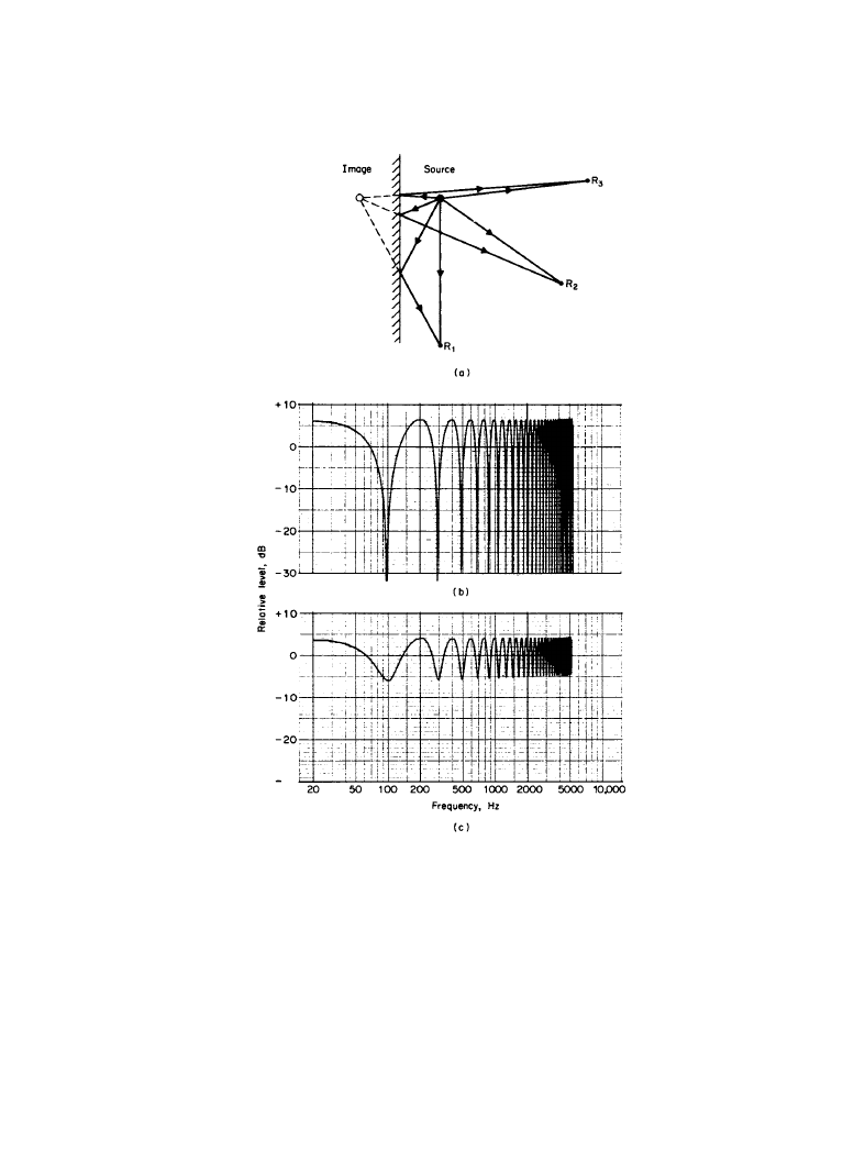
Figure 1.2.2 shows the direct and reflected sound paths for an omnidirectional source and
receivers interacting with a reflecting plane. Note that there is an acoustically mirrored source,
just as there would be a visually mirrored one if the plane were optically reflecting. If the dis-
tance traveled by the direct sound and that traveled by the reflected sound are different by an
amount that is small and is also small compared with a wavelength of the sound under consider-
ation (receiver R
1
), the interference at the receiver will be constructive. If the plane is perfectly
reflecting, the sound at the receiver will be the sum of two essentially identical sounds and the
SPL will be about 6 dB higher than the direct sound alone. Constructive interference will also
occur when the difference between the distances is an even multiple of half wavelengths.
Destructive interference will occur for odd multiples of half wavelengths.
As the path length difference increases, or if there is absorption at the reflective surface, the
difference in the sound levels of the direct and reflected sounds increases. For receivers R
2
and
R
3
in Figure 1.2.2, the situation will differ from that just described only in that, because of the
additional attenuation of the reflected signal, the constructive peaks will be significantly less
than 6 dB and the destructive dips will be less than perfect cancellations.
For a fixed geometrical arrangement of source, reflector, and receiver, this means that at suf-
ficiently low frequencies the direct and reflected sounds add. As the wavelength is reduced (fre-
Downloaded from Digital Engineering Library @ McGraw-Hill (www.digitalengineeringlibrary.com)
Copyright © 2004 The McGraw-Hill Companies. All rights reserved.
Any use is subject to the Terms of Use as given at the website.
Sound Propagation
Sound Propagation 1-25
Figure 1.2.2
(
a) Differing direct and reflected path lengths as a function of receiver location. (b)
The interference pattern resulting when two sounds, each at the same sound level (0 dB) are
summed with a time delay of just over 5 ms (a path length difference of approximately 1.7 m). (
c)
The reflection signal has been attenuated by 6 dB (it is now at a relative level of –6 dB, while the
direct sounds remains at 0 dB); the maximum sound level is reduced, and perfect nulls are no
longer possible. The familiar comb-filtering pattern remains.
Downloaded from Digital Engineering Library @ McGraw-Hill (www.digitalengineeringlibrary.com)
Copyright © 2004 The McGraw-Hill Companies. All rights reserved.
Any use is subject to the Terms of Use as given at the website.
Sound Propagation